I spend my days (at least a fair number of them) standing next to a CNC milling machine producing parts for prototypes and models destined for design review meetings and industry conventions. I do not work on the cutting edge of machining technology, but I have almost a decade of experience with such machines and follow many of the very interesting developments in machine tool technology.
While explaining to a visitor how the machine “knows” where the part is, it occurred to me one day that many people have very little exposure to the machinery that literally builds the world around them – including so many of the wristwatches’ components.
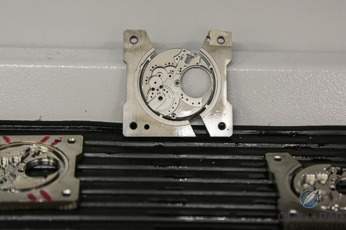
A base plate milled by a CNC machine at UWD in Dresden, part of the Tempus Arte group
After revisiting my previous articles covering 3D printing, the types of machines, and what they are good at (and not so good at) doing, I decided that it might be interesting, and beneficial, for watch lovers to know a bit more about the machining and turning responsible for how their watches come to be in the modern era.
While I won’t be getting into some of the details here that I cover with the 3D printing articles, I do want to break down milling machines and turning centers, the multi-axis machining that has become a cornerstone of modern fabrication.
Thanks to our co-founder Ian Skellern, Quill & Pad readers have been given a quick primer to CNC machining in 350 Processors And 90,000 Watts Of Power Just To Mill A Curved Line? This article expands upon the subject, focusing on the technical details that I love to ramble on about so much. So let’s begin with what multi-axis machining is and why it is so important.
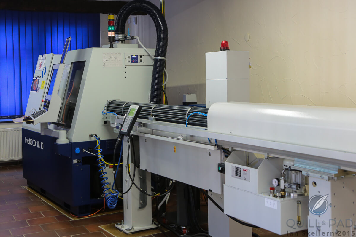
CNC machine at UWD in Dresden, Germany
First steps
Multi-axis machining, for all practical purposes, refers to a large majority of milling machines. “Multi-axis” literally means “multiple axes.” The most basic machines have at least three axes (or two, but we’ll get to that) and usually are not strictly purpose-built for only a single operation.
Those types of machines appear in production lines, where a part (or raw material) will arrive on a conveyor belt or via a robotic placement and have only one process performed on it. That could be a hole drilled or the surface planed down to a specific depth, but nothing more.
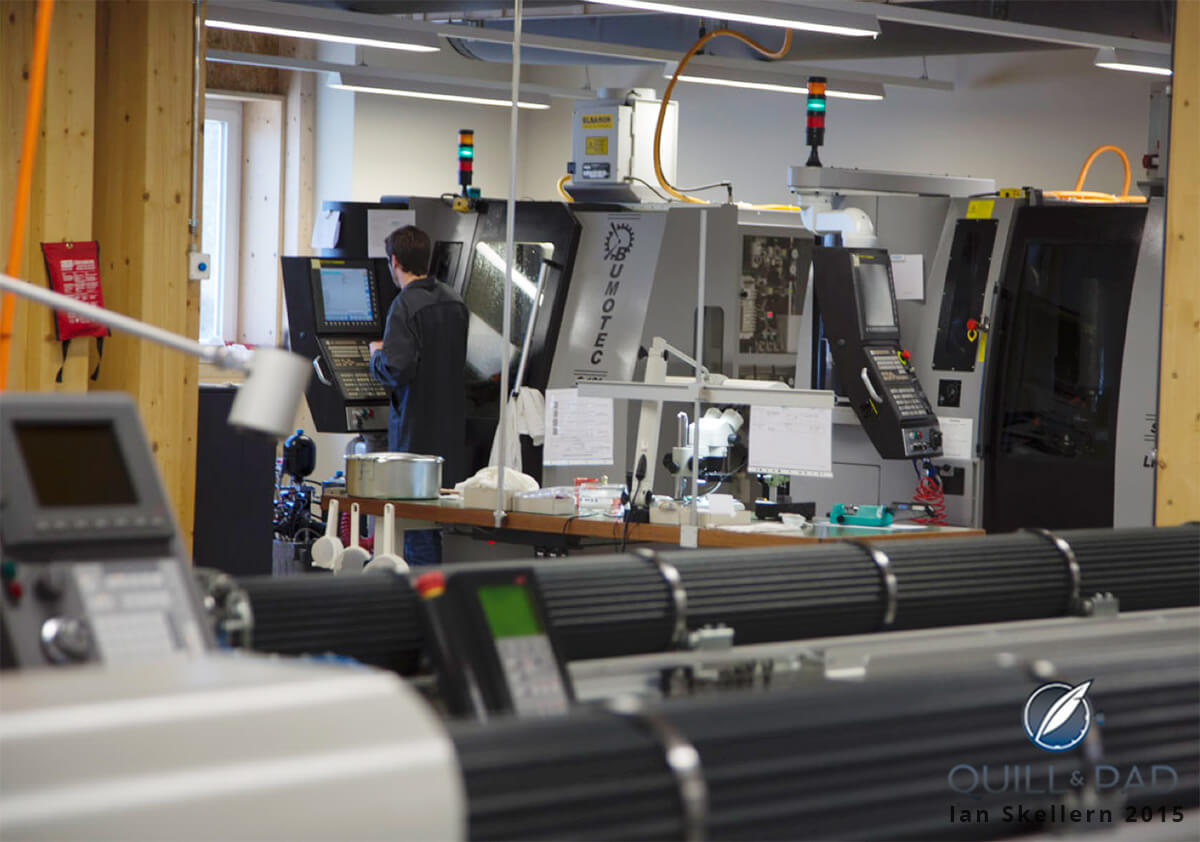
CNC machines in the background with automatic lathes in the foreground at Manufacture Romain Gauthier
In this context, it provides a limited function as part of a larger production process. These machines are not what we will be discussing here.
Multi-axis machines start off from the basic milling machine and the basic lathe and expand from there. A milling machine, be it manual or CNC (Computer Numerical Control), has at least three directions of movement for cutting: the X, Y, and Z
The X and Y (in most cases) describe the left and right, forward and backward direction of travel of the support bed; work piece and vises are clamped rigidly on the support bed, while the milling process takes place. The Z axis refers to the vertical motion of the spindle, which moves up and down while holding a milling tool, drill bit, threading tool, or other specialty tool (or even a measuring probe, ooh).
This automatic lathe at UWD in Dresden looks ready to take part in a downhill speed trial (or the next ‘Star Wars’ movie)
A basic lathe is technically very similar to a milling machine, but with one main difference: the location of the part. On a mill, the part is clamped in place while the tool rotates in the spindle. On a lathe, the part being milled rotates rotates in the spindle while the tools are sliding left and right and forward and backward on a carriage and cross slide to meet the part.
The designation for the axes changes, but the reality is fairly similar. There are still (technically) three axes of possible movement, but only the Z and X axes are used while the Y is generally considered static on a basic lathe. The reasoning might help you better remember why each axis is labeled as it is.
On a basic lathe and milling machine, the Z axis is always parallel to the axis of rotation, be it the spindle holding a tool on the mill or the spindle holding the part on the lathe. The X and the Y are always perpendicular to each other and to the Z axis.
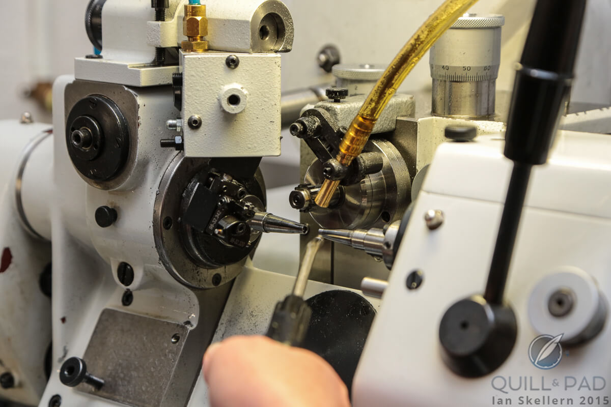
The business end of an automatic lathe at Nomos Glashütte, in which the component being turned spins while the cutting tool is stable
On a lathe, this is where it gets a little different. The carriage (where the cutting tool is mounted) moves along the Z axis (left and right on the lathe as you look at it) parallel to the rotation of the spindle. The cross slide (the adjustable carriage on top of the main carriage) moves in the X axis, moving forward and backward from the work piece, perpendicular to the Z axis. The Y axis then raises or lowers the tool from the carriage.
This axis is static on a basic lathe as the tool needs to be centered and rigidly mounted on the mid line of the rotating part. For this reason, a basic lathe is actually considered a two-axis machine.
On to the fourth dimension. And, no, that dimension is not time.
This is where things start to get really fun and where multi-axis machining becomes a little bit of magic. On a milling machine, you can create a fourth axis of rotation, which usually falls parallel to the X axis.
If only the fourth axis is being utilized, this is accomplished by adding a rotary table aligned with the X axis and perpendicular to the Y axis. This is called the A axis.
This rotary table, controlled along with the other axes of rotation, allows for a part to be indexed (rotated a specific number of degrees for equal partitions) and then machined using a standard three-axis program. Or it moves with live rotation during machining (called continuous fourth axis), allowing for off-axis components and features to be achieved or for complex 3D shapes to be milled around a circumference.
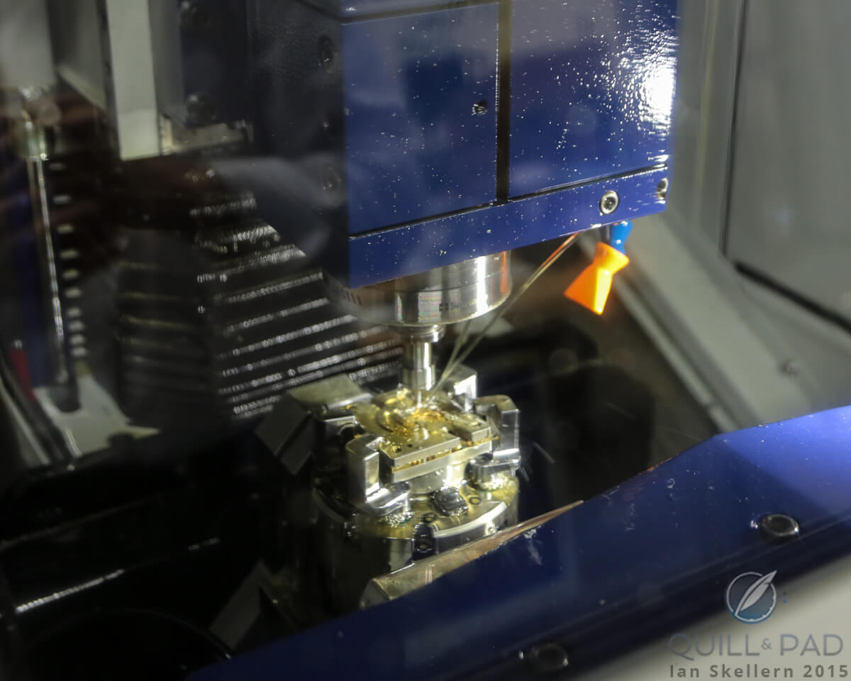
A CNC machine milling a base plate at UWD in Dresden with the component securely held on a trunnion table
This can also be accomplished with a trunnion table, which is a U-shaped table, supported on both ends, to which a horizontal vise can be mounted. It can be rotated around the A axis just like the rotary table, but supporting the part in a different way.
On a lathe, things get even more complicated. To have a fourth axis on a lathe (and that pesky third axis), you need to have live tooling. “Live tooling” means a second spindle rotating with a second cutting tool.
A four-axis lathe adds a second X axis to the Y axis, usually labeled X2 (and, no, that actually is not the fourth axis), which allows a live tool to be moved in and out from the part and raised above and below the center line. This sounds awesome, but it actually does very little differently from the basic lathe because you need to control precise rotational position of the work piece to utilize it properly. This is technically where the fourth axis comes in, and it is called the C axis.
The C axis allows the lathe to index or continuously rotate (like the A axis on a four-axis mill), while the live tooling moves in and creates geometry that was previously impossible to make with a basic lathe such as slots (horizontal or parallel to the axis of rotation), flats, cross holes, and other interesting features.
Now, as a literalist, I would venture that this lathe technically has five axes of movement, but that is only if the live tooling is mounted on its own carriage independent of the Z and X axis tooling. If not, then the X2 axis is really a negative value for the original X axis, since when one moves in, the other moves out. There are examples of both machines out there, so really the functionality is more important for programmer’s sake and less for machine capability.
Given either setup, the best way to think about a four-axis lathe with Y and C axis is to see a standard two-axis lathe with the added ability of a four-axis mill in the same machine.
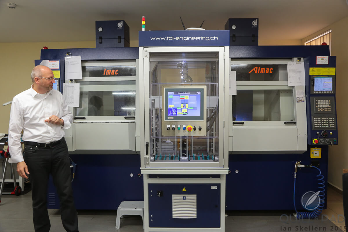
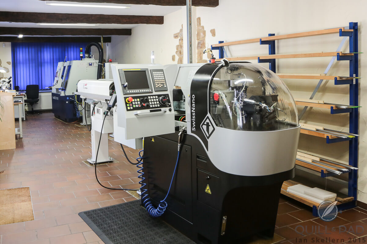
Tempus Arte technical director Marco Lang looks at the state-of-the-art CNC machine at UWD, which actually comprises two CNC machines (5-axis on the left and 3-axis on the right) on either side of a central shared tool manager
The fifth axis . . . and beyond!
The fifth axis is considered by many (not in the industry) to be the crowning achievement of multi-axis machining technology. We’ll learn in a bit why that is not the case, but why it really is as much as you could want unless you are doing HIGHLY specific parts with very complicated and possibly strange geometry. But I’m getting ahead of myself.
The fifth axis on a milling machine is a rotation of the second perpendicular axis (Y axis). This is commonly achieved with a dual-axis trunnion table. Like the four-axis trunnion table before, it is a U-shaped table, but in the center of the table is a rotary table allowing the part to rotate around the A axis and now the B axis.
This allows the machine to reach five of the six sides of a typical part in one setup, greatly reducing setup time (which is no insignificant consideration) and maintaining positional accuracy since the operator does not need to manually relocate the part to machine each individual side.
Needless to say, this capability has revolutionized the machining industry as it creates the ability to machine off-axis features in any axis very simply. There are very few parts that cannot be created with this type of setup, and if one is required, the five-axis machining center still saves greatly on setup time for the further operations.
On a lathe, like I said before, this is where the five-axis designation comes into play. If the live tooling is controlled separately from the static tooling, then the machine truly has the fifth axis in the X2 axis. This machine does have a fair amount more capability over a true four-axis lathe, but again it relates more specifically to part programming and the ability do two things at once. It does fall short of a five-axis milling machine, and you will see why shortly.
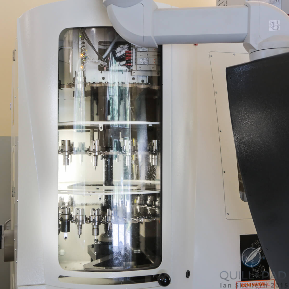
Racks attached to this CNC machine at UWD contain different drilling and milling blades and tools, which are automatically changed as necessary
Seriously beyond
Moving beyond the fifth axis . . . hold on a minute. Yeah, I said moving beyond the fifth axis! When we reach the sixth axis, we are talking about the ability for the Z axis on a mill and the Y axis on a lathe to rotate perpendicular to the axis. So a milling machine spindle is able to rotate left and right, and the live tooling on a lathe will do the same.
The axis, on a mill, is called the C axis, and on a lathe is called the A axis, though at this point some programmers and manufacturers will actually disagree on call-outs (at least I have noticed this, despite the availability of “accepted” definitions).
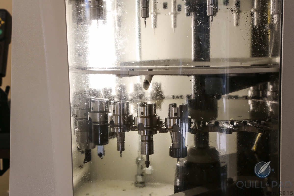
Racks attached to the CNC machine contain different drilling and milling blades and tools, which are automatically changed as necessary
Regardless of the call-out, this sixth axis of rotation is where the lathe finally catches up with the geometric capabilities of the milling machine as it now accomplishes holes and features at any angle to any axis, just like a five-axis mill.
The capabilities of a six-axis mill are not necessarily greatly enhanced, though it now has the ability to program specifically for the exact point where it wants the cutting tool to contact the work piece and vice versa.
This might not seem like a big deal, but it becomes very important for complicated pocket shapes and for maintaining tool life, surface finish, and proper feeds and speeds.
Machining nerd side-note: feeds and speeds refer to the speed at which the tool is rotating, how fast it is being moved across the surface of the material (in inches/meters per minute on a mill or by surface feet/meters per minute on a lathe), and the amount of material being removed (depth or rotationally) by each cutting tooth (in inches/mm per tooth on a mill or inches/mm per revolution on a lathe).
After the sixth axis, things get pretty crazy as machines add more tools moving at once and more work holding solutions for multiple setups at once. Machines can have 7, 8, 9, 10, 11, or 12 axes of movement, possibly more that create the ability to machine multiple places and multiple parts at once (sometimes called back machining). These machines leave the realm of being a milling machine or a lathe and become machining centers.

This is the universe that Swiss-style screw machines inhabit, with multiple fixed-point tools and multiple live tools interacting with a part at the same time. These multi-axis machining centers can have multiple lathe-style spindles and the ability to transfer a part, automatically, from one to another to perform secondary operations from other angles not previously available, all while the other spindle is creating another part.
The answer to the ultimate question of life, the universe, and everything
After hearing about all these machines, and seeing some rather incredible demonstrations, I think the usefulness of multi-axis machining is rather apparent, but in case it still eludes you, let me summarize. These machines allow for the ability to machine dang-near anything that is machinable in our physical world. For any component, almost anything you can think up, there is a machine that can machine it in one way or another.
That means that the most complex watch case can be machined in less than a minute on the right machine (okay, that was an overstatement for sure; but these machines do have the ability to create highly complex parts in minutes, given many, many other factors. See the comments for more details). It means that, given a precise enough machining center and enough axes, even a balance wheel assembly, with all of its features, could be made automatically in a single machine.
Now we know that we wouldn’t want the entire assembly to be of one material, but the capability is there. And we know that Rolex uses highly specialized multi-axis machines to manufacture almost every component to ensure precision and repeatability.
The truth is that multi-axis machining is mostly just a time-saver for production, as almost every part made on one of these super-advanced machines could be made (and probably was at one point) on a “simple” three-axis machine by a skilled machinist using his knowledge, a ton of math, and hours (or days) of patience and manual setup time. These machines do all of that work for us.
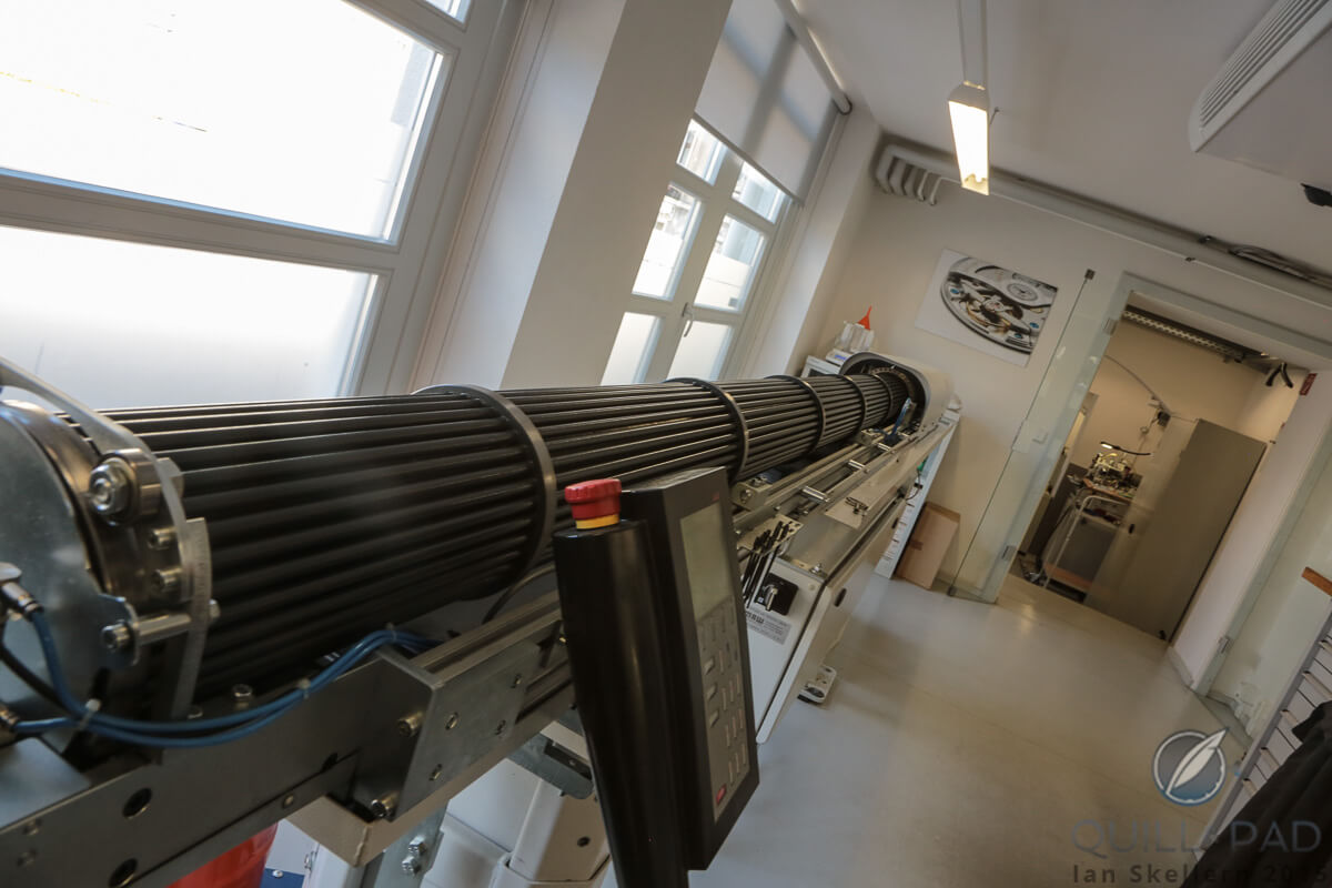
These Gatling-gun type tubes at the Nomos Glashütte manufacture house rods of brass and other alloys that feed into the automatic lathe to be transformed into components
That could be seen as a good thing or a bad thing, given your profession. As a machinist myself, and as an aspiring watchmaker and designer, I understand the realities of both. Being able to utilize these machines can speed up the life cycle of product development, but it cannot replace skilled knowledge and experience. They go hand in hand.
Hopefully this primer into multi-axis machining gave you a bit of knowledge and left a lot of questions for you to explore. This was not meant to be a “how machining works” or “the difference between a lathe and a milling machine” article. I wanted to cover the breadth of machinery types and capabilities without focusing too much on minutia as every machine is unique in its functionality.
But what is covered here should help to know where to start when looking at different machines, capabilities, and uses. There is so much more out there to discuss and explore, and I hope I have sparked the interest of you, the reader.
Much of this technology is, even to me, in the realm of fantasy. And I am keeping my fingers crossed to be able to play with these machines in my future. Until then, I’ll stick to my three-axis CNC mill and daydream. Oh boy, look at the spindles on that beauty . . .
For more reading please see:
350 Processors And 90,000 Watts of Power Just To Mill A Curved Line? CNC Primer
Focus On Technology: 3D Printing, What Is It Really?
Focus On Technology: 3D Printing, What Is It Really? Part Deux
Leave a Reply
Want to join the discussion?Feel free to contribute!
A great exposé with masses of information on a fascinating subject that usually never gets coverage! We often forget the incredible potential of these amazing machines and I still find it captivating to see them move and work with the accuracy of mere microns at such high speeds as they do. So the ‘nerd’ in me was very happy to read your excellent article on this ignored subject matter.
However, I would dare say that there is just one small statement which is quite incorrect in your article that I feel needs balancing: …..”That means that the most complex watch case can be machined in less than a minute on the right machine”….. Well, with all respect, it is absolutely impossible to make a complex watch case design in one minute with such machines, even the most advanced. With all this mechanical mastery, the milling alone of a complex case design still requires 2-3 days of work. And let us not forget this is just the milling – it excludes the preliminary stages of creating the pre-form billet as well as the later stages of finishing, polishing, water resistance testing and quality control. At top Swiss factories such as Donzé Baume or ProArt, a complex three part case milling takes about 2-3 days. These machines are certainly amazing, but they are not capable of just popping out watch cases like doughnuts at a bakery every minute by a long shot!
I also forgot to add that the background preparation to milling work, such as creating a number of specialized cutters by hand, and the programming and setup takes days as well. For certain high tech composite materials and titanium, cutters wear down quite fast and this can also require partial tooling replacements every 20-25 cases or so once the reserve cutters in the machine’s tooling system have been used up.
Exactly as you mention, without all the ‘worker bees’ taking care of all these aspects, these machines would not produce much at all. Count all these aspects together with the work of the people involved and you are talking about 2 weeks for a complete complex case production, with 2-3 days allocated for the milling of such designs and perhaps 1-2 days of milling for simpler, classical outlines.
Regards and thanks again for your fine overview of this highly complex subject material !
Theodore Diehl
Company Spokesman & Horologist
Richard Mille Watches
P.S. I forgot to mention that the milling of just a Richard Mille cartouche with raised letters on the back bezel still takes about 45 minutes of milling work on the most highly advanced machines available in 2015….!
Mr. Diehl,
Thank you very much for the comment, and I will have to admit you caught me in my hyperbole! You are definitely correct that a complex case could never be made in a minute. There are too many components, too many features, and too many steps that need to be verified for tolerances.
But it is also true is that, barring all the setup time, adjustments, and tool replacements, a very simple case, like a two part case made from solid billet rod, could truly be machined on an 11 axis milling center in a matter of minutes. Sometimes my excitement gets away from me! From a machining standpoint, if we only count the actual program run time of a simple solid case, I personally know I could program that to run in a very short amount of time. But of course, once you add in all the features required for a majority of watches, that figure goes out the window, fast. And of course that is not taking into consideration the entire world of machining specifics for special materials, machine engraving, or automated finishing. I will look at correcting that to reflect my hyperbolic error.
In the end, this was meant to be a very light primer, getting into the amazingness of the machines and not a list of the entire machining process, because, as your comment proved, that list could go on for days! I know when I teach coworkers how to machine, and I start telling them little bits of knowledge specific to each aspect, I begin to realize that I could write a book and barely scratch the surface of machining technology.
I’m glad there are people like you (and me a little bit) that will push to make those details known, so that everyone can realize why highly specialized products such as these watches take so much time and effort to create. It really is a highly complex subject and I knew I had to leave so much out, so thank you again for your addition to the article!
My regards,
Joshua Munchow
As you mentioned, on a lathe, things get complicated and you need to had live tooling. This allows you to have a second spindle rotating with a second cutting tool. It would be interesting to see all of these moving parts working in sync.
This is a very informative blog, thanks for sharing about focus on technology multi axis machining a primer. It will help a lot; these types of content should get appreciated. I will bookmark your site; I hope to read more such informative contents in future.
Thank you for this suitable article about focus on technology multi axis machining a primer, it will help me and people like me looking for the same. I appreciate your effort for taking time to do your research and present these details before us. Really nice way to present this content, very appreciative!!