Making The Escapement, Remontoir, And Timing For Derek Pratt’s Reconstruction Of John Harrison‘s H4, The World’s First Precision Marine Chronometer (Part 3 of 3)
by Ian Skellern
This is part 3 of a three-part series about Derek Pratt’s reconstruction of John Harrison’s Longitude Prize winning H4, which was the world’s first precision marine chronometer. This article was first published in the The Horological Journal (HJ) in April 2015, who we thank for graciously granting permission to republish on Quill & Pad.
To learn more about Derek Pratt please see The Life And Times Of Legendary Independent Watchmaker Derek Pratt, Derek Pratt’s Reconstruction Of John Harrison‘s H4, The World’s First Precision Marine Chronometer (Part 1 of 3), and Making The Diamond Pallets For Derek Pratt’s Reconstruction Of John Harrison‘s H4, The World’s First Precision Marine Chronometer (Part 2 of 3).
Part 3: The Escapement, Remontoir, And Timing
By Roger Stevenson FBHI
Escapement
With the diamond pallets made, we pressed on in order to have the watch ticking, albeit without the remontoir and before all the jeweling was completed.
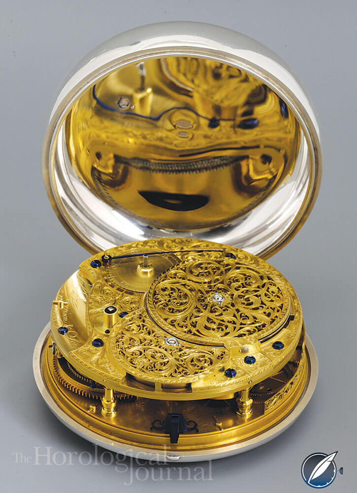
Derek Pratt’s H4 showing the completed movement and Charles Scarr’s piercing and engraving
The large balance wheel (50.90 mm diameter) was made from hardened, tempered, and polished gauge plate. The wheel was clamped between two plates for hardening, and this helped to reduce distortion.
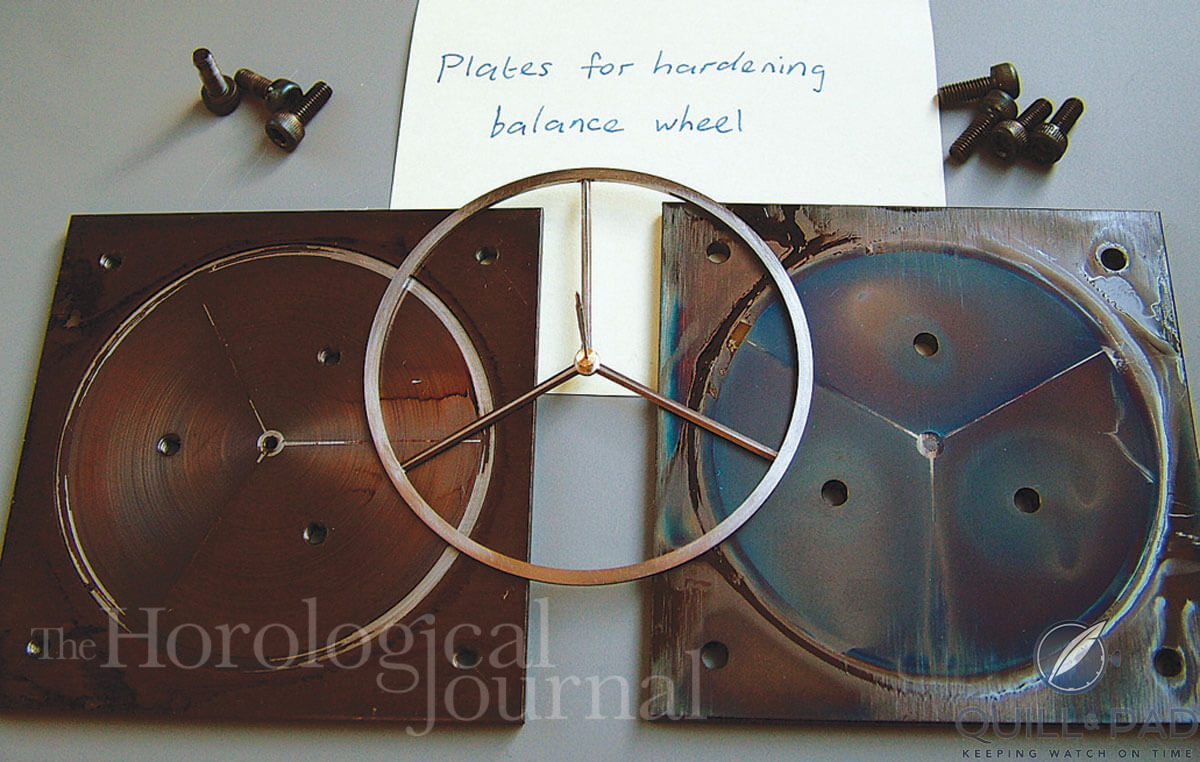
Balance wheel hardening plates for Derek Pratt’s H4 showing the balance at a later stage with the staff and collet in place
The balance staff is a long slender arbor of 21.41 mm waisted down to 0.4 mm where the pallet and balance wheel collets are mounted. The staff was turned on a watchmaker’s lathe and finished in the turns. The brass collets for the pallets are secured to the staff with cotter pins and the pallets were shellacked into D-shaped holes in the collets.
These holes were produced in a brass plate using our EDM (electrical discharge machine). A copper electrode shaped to the section of the pallet was sunk into the brass and then the hole for the staff and the outside profile was machined in a CNC milling machine.
The final finishing of the collets was done by hand using files and steel polishers, and the cotter pin holes were made using an Archimedes drill. This was an interesting mixture of high and low-tech work!
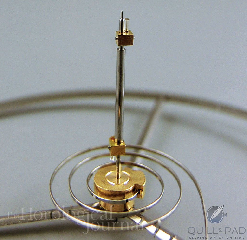
Balance complete with diamond pallets and trial balance spring for Derek Pratt’s H4
The balance spring has three complete turns and a long straight tail. The spring is tapered, being thicker at the stud end and tapering toward the collet at the centre. Anthony Randall had given us some 0.8 percent carbon steel that had been drawn to a flat section, and this was stoned to taper to the dimensions of the original H4 balance spring. The thinned spring was placed in a steel former for hardening.
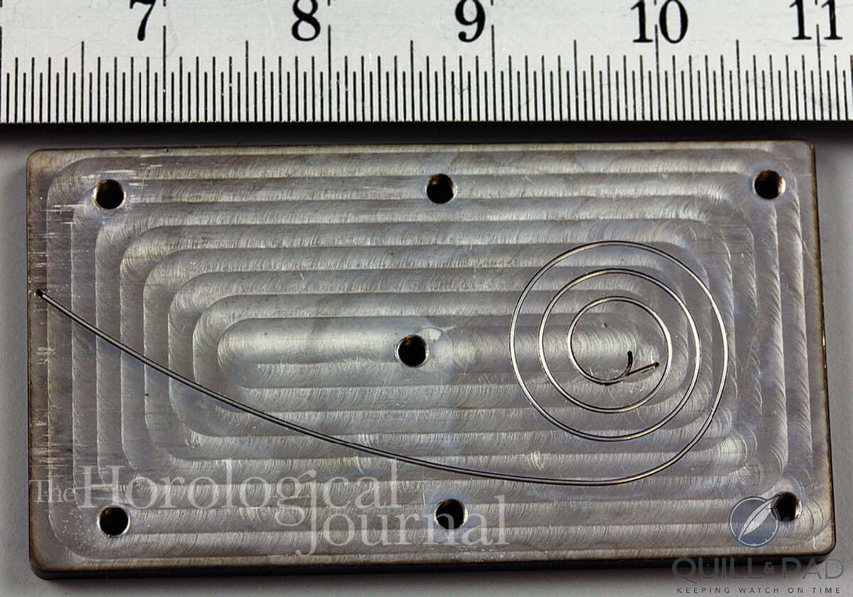
Former for hardening the balance spring for Derek Pratt’s H4
We had good photos of the original spring, which enabled us to draw out the shape and CNC mill the former. With such a short spring, one would expect the balance to wobble about violently when the staff was upright but not constrained by the jeweling on the balance bridge. However, owing to the long tail and the tapering of the spring, if the balance and spring are set vibrating, just supported on the lower pivot and with the upper jeweling removed, the balance staff stands surprisingly steady.
The balance and spring have a large point of attachment error, as would be expected from such a short spring, but the effect is reduced by the tapering thickness of the spring and its long tail.
Remontoir
Having got the watch running, being driven directly from the train, the next stage was to make and fit the remontoir. The axis of the fourth wheel is an interesting three-way junction. There are three co-axial wheels at this point: the fourth wheel, contrate wheel, and center seconds drive wheel.
The internally cut third wheel drives the fourth wheel in the normal manner, and the fourth in turn drives the remontoir train consisting of a locking wheel and a fly pinion. The contrate wheel is driven from the fourth arbor via the remontoir spring, and the contrate drives the escape wheel.
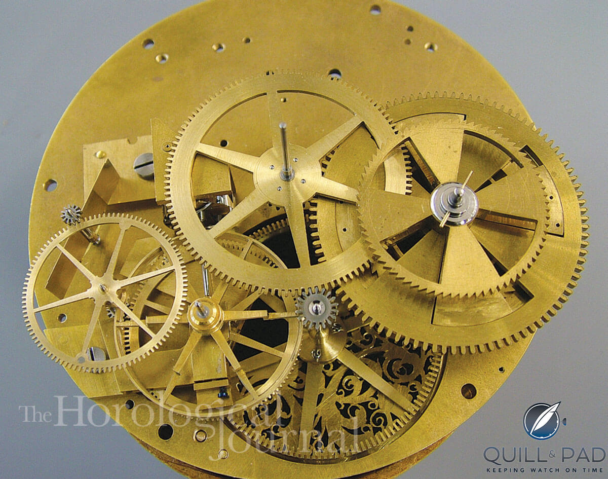
Fourth wheel junction where drive is given to the remontoir, the contrate wheel, and to the center seconds wheel for Derek Pratt’s H4 reconstruction
The contrate wheel has a long slender arbor that passes through the hollow arbor of the fourth wheel, and the seconds driving wheel is mounted at the dial side of the contrate arbor.
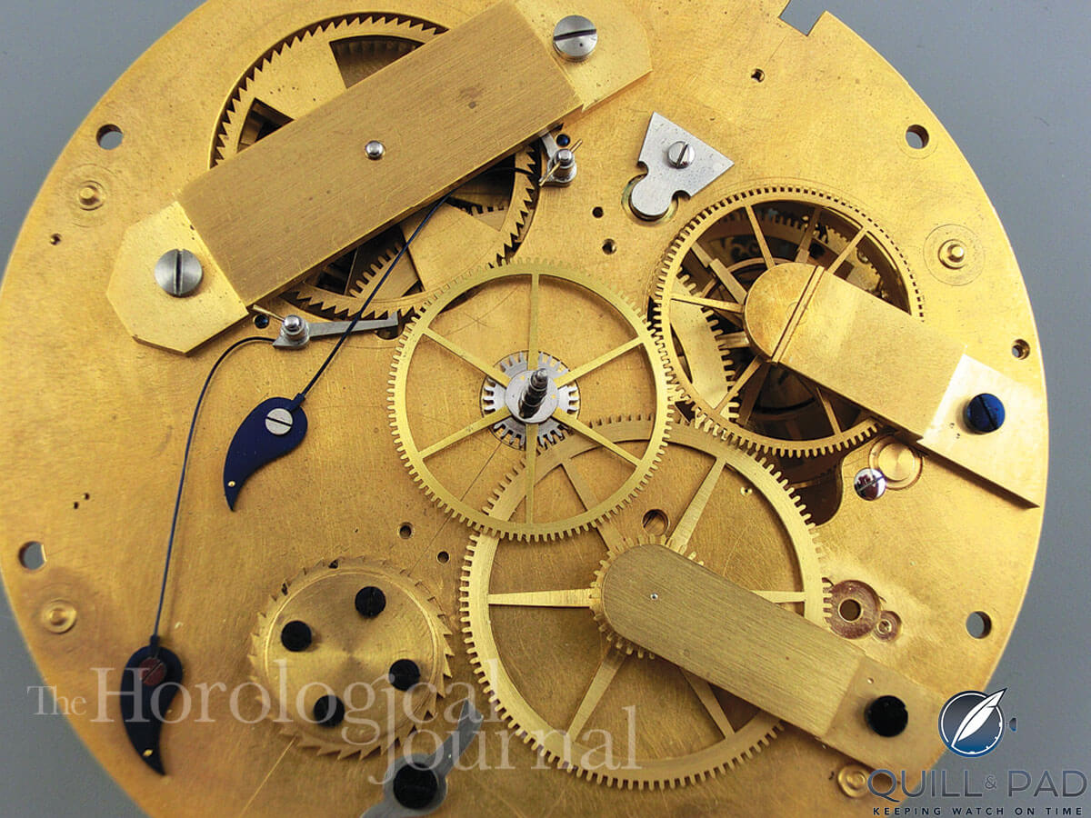
Drive from the fourth wheel to the center seconds wheel for Derek Pratt’s H4 reconstruction
The remontoir spring was made from a watch mainspring measuring 1.45 mm high x 0.08 mm thick and approximately 160 mm long. The spring is held in a brass cage mounted on the fourth wheel arbor. The spring has to sit in the cage with open coils, not bunched up against the wall of the barrel as it would normally be in a watch barrel. To achieve this, we used a former similar to the one used to make the balance spring, in order to set the remontoir spring to the correct shape.
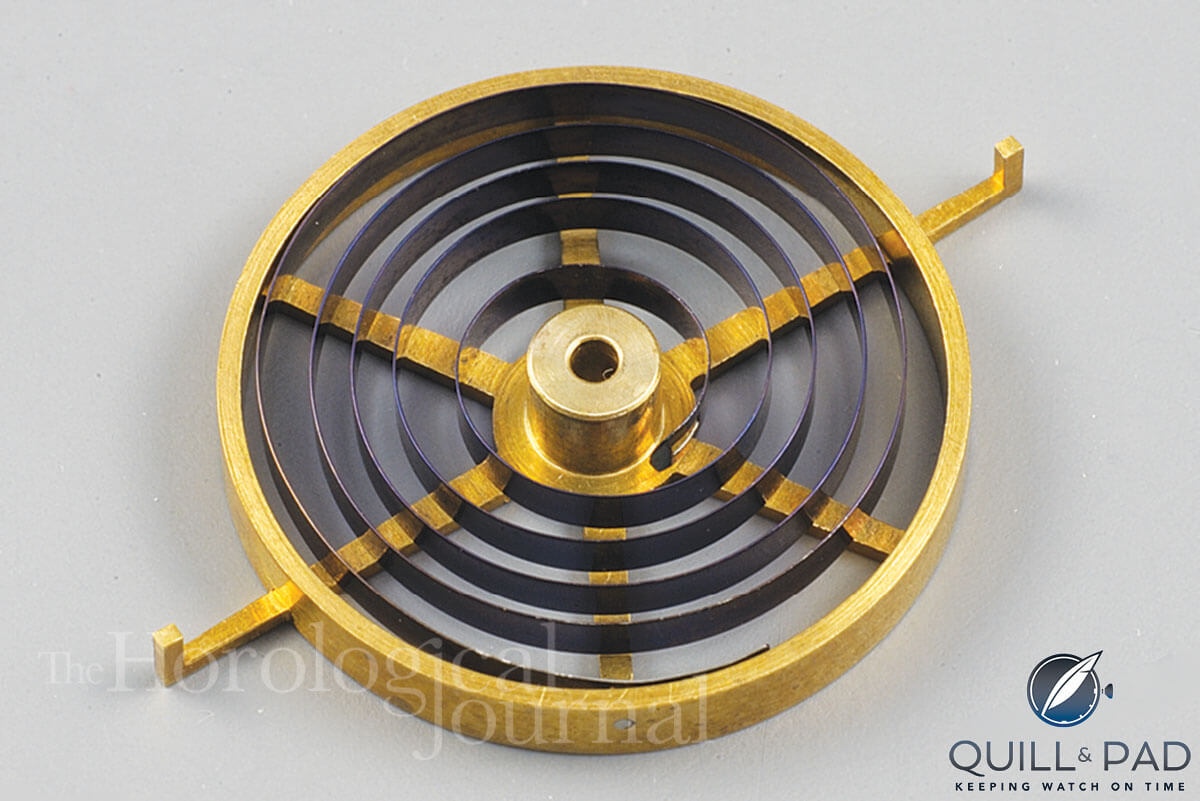
Remontoir spring in its cage for Derek Pratt’s H4
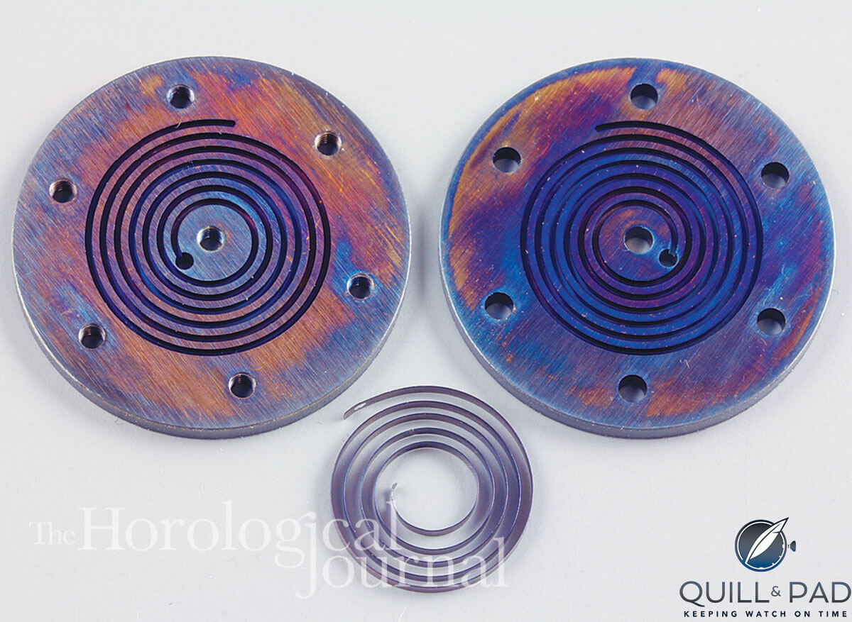
Formers for the remontoir spring for Derek Pratt’s H4
The remontoir release is controlled by a pivoted detent, locking wheel, and a fly to govern the speed of the remontoir rewind. The detent has five arms mounted on the arbor; one arm holds the claw that is engaged by release pins on the contrate arbor. As the contrate rotates, one of its pins gently lifts the detent to the point where another arm releases the locking wheel. The locking wheel is then free to rotate one revolution in order to allow the remontoir spring to re-wind.
A third arm has a pivoted roller that bears against a cam mounted on the locking wheel arbor. This keeps the detent and claw free from the path of the release pins whilst rewinding takes place, and the contrate wheel keeps turning. The two remaining arms on the detent are counterbalances to poise the detent.
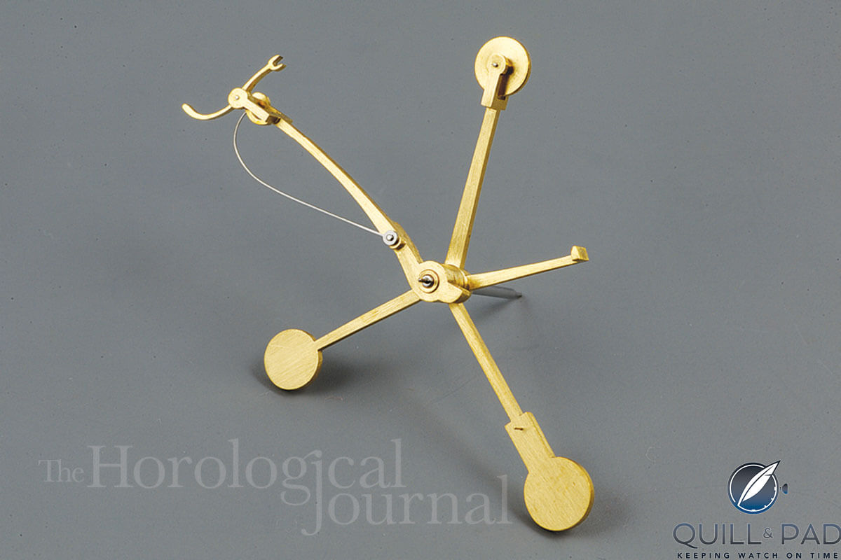
Remontoir detent for Derek Pratt’s H4
All of these components are quite delicate and required careful hand-filing and finishing but were very satisfying to work on. The fly vane is 0.1 mm thick but has a relatively large area; this proved to be a tricky part to make as the central boss is one with the vane.
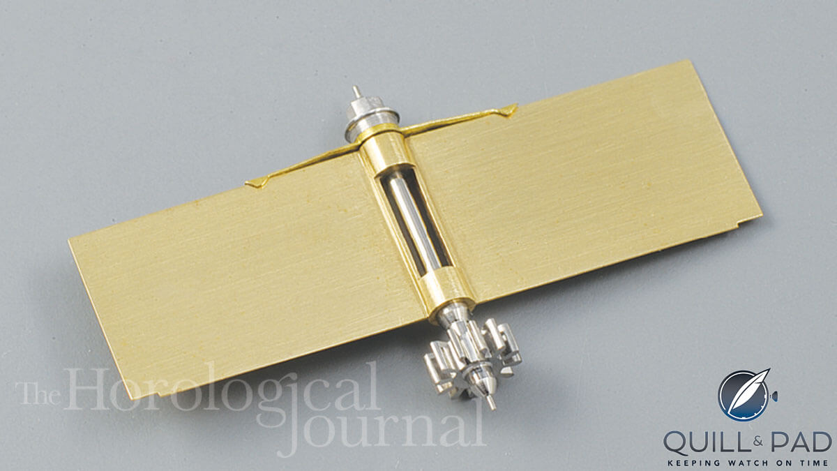
Remontoir fly for Derek Pratt’s H4
The remontoir is an ingenious mechanism and fascinating to watch, and since it rewinds every 7.5 seconds you don’t have to wait very long for some action!
James U. Poole overhauled the original H4 and wrote an interesting report of his work for the Horological Journal in April 1891. In speaking of the remontoir mechanism, he states: “No hints on this very essential point were given by Harrison in his description of the construction of the watch. I had to grope my way by a succession of troublesome experiments, and for several days despaired of ever being able to put it together again. The action of the remontoir train is so mysterious that it cannot be properly understood, even while being closely observed, and I doubt if it is really useful.”
Poor man! I like his disarming honesty over his struggles and perhaps we have all felt similar times of frustration at the bench!
Motion work
The motion work is conventional for the hours and minutes, which are driven from the cannon pinion mounted on the center arbor, but the center seconds hand is carried by a wheel that is placed between the cannon pinion and the hour wheel. The centre seconds wheel rotates on the cannon pinion and is driven by a wheel of the same count that is mounted on the dial end of the contrate arbor.
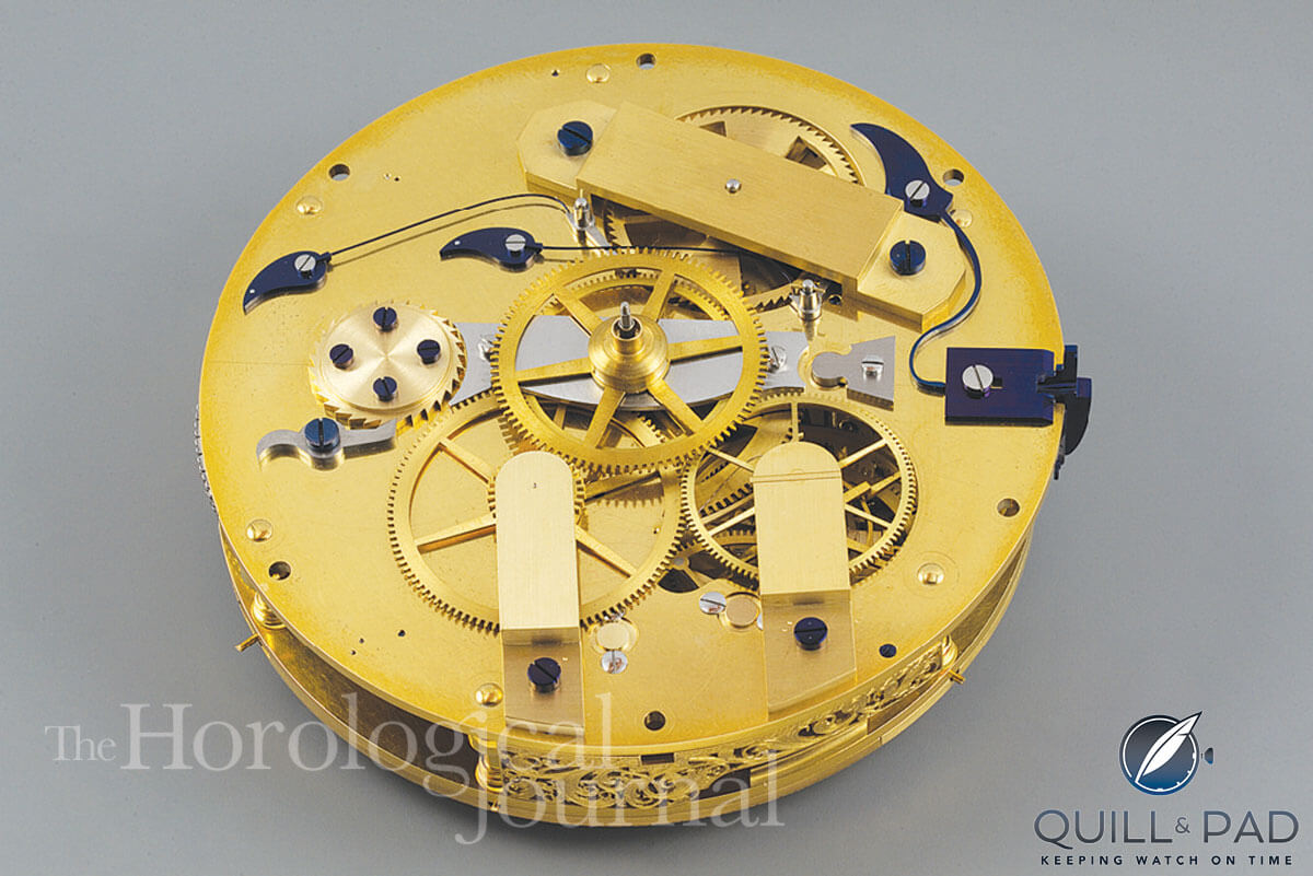
H4’s motion work for Derek Pratt’s H4 showing the shows the cannon pinion, minute wheel and the drive to the center seconds wheel
The depthing of the center seconds drive is as deep as possible to ensure that the seconds hand doesn’t “dither” as it runs, but it also needs to be free running. On the original H4, the driving wheel is 0.11 mm larger in diameter than the driven wheel, although both have the same number of teeth. It seems that the depthing was deliberately made too deep and then the driven wheel was “topped” to provide the freedom needed. We followed a similar procedure to allow free running with minimum backlash.
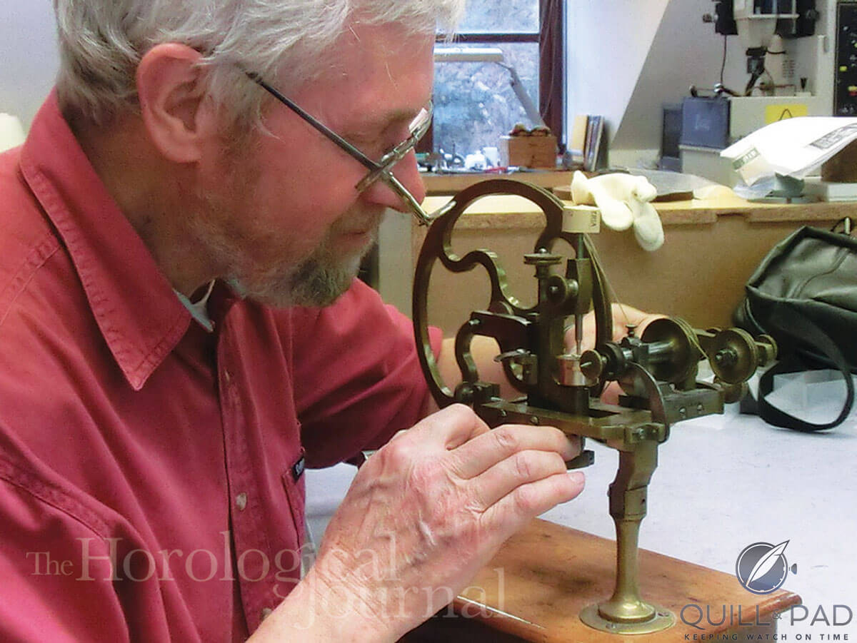
Using the topping tool to obtain minimum backlash in driving the center seconds hand for Derek Pratt’s H4
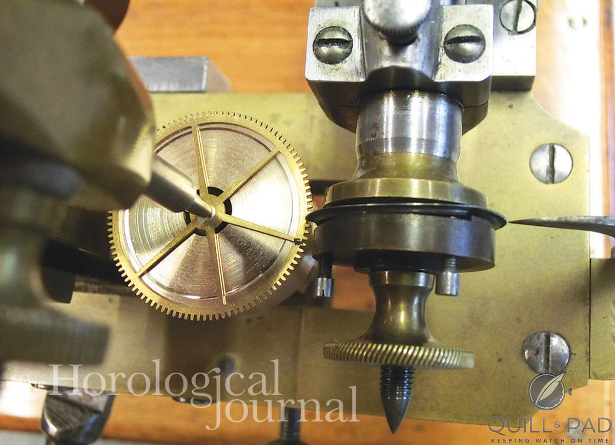
Topping the center seconds drive wheel for Derek Pratt’s H4
Derek had made the three hands, but they needed some finishing. Daniela worked on the hour and minute hands, polishing, then hardening and tempering and finally bluing in bluing salts. The center seconds was left polished and not blued.
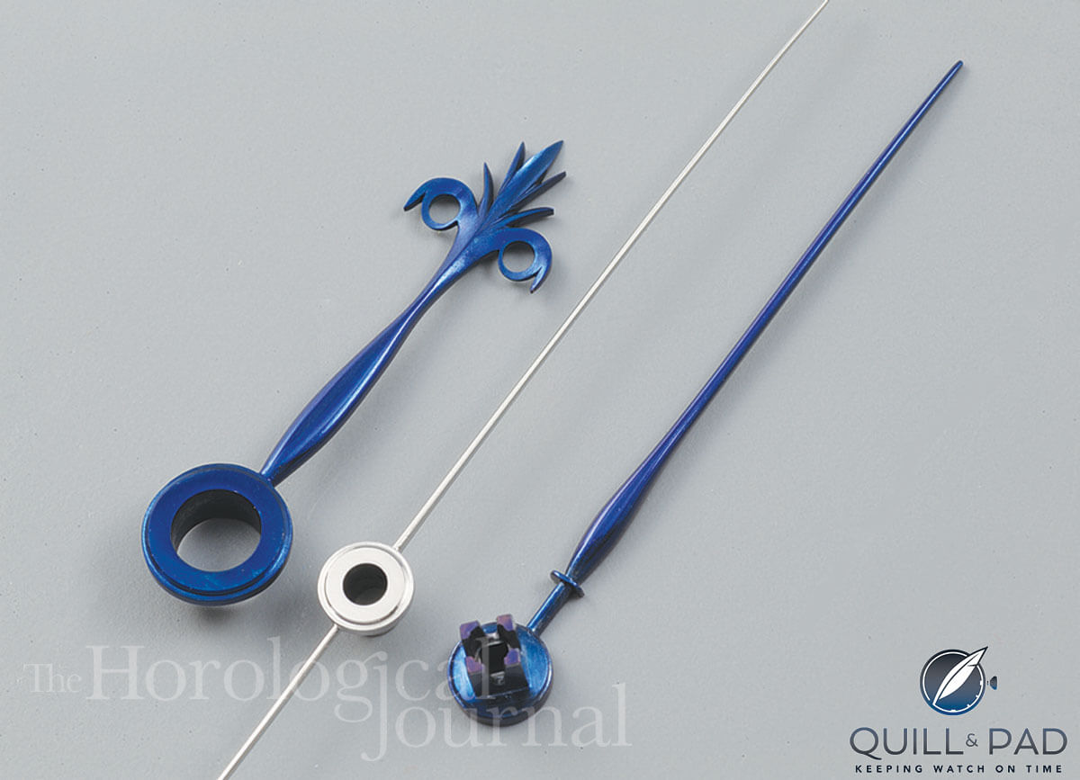
Hour, minute, and second hands for Derek Pratt’s H4 reconstruction
Compensation and isochronal adjuster
Harrison originally intended to use a rack and pinion regulator in H4, as was common in verge watches of the time and as shown in one of the drawings produced when the watch was examined by the Board of Longitude. He must have abandoned the rack early on, although he had used it in the Jefferys watch with a bimetal compensation curb as first used in H3.
Derek wanted to try this arrangement and made a rack and pinion and started to make the compensation curb.
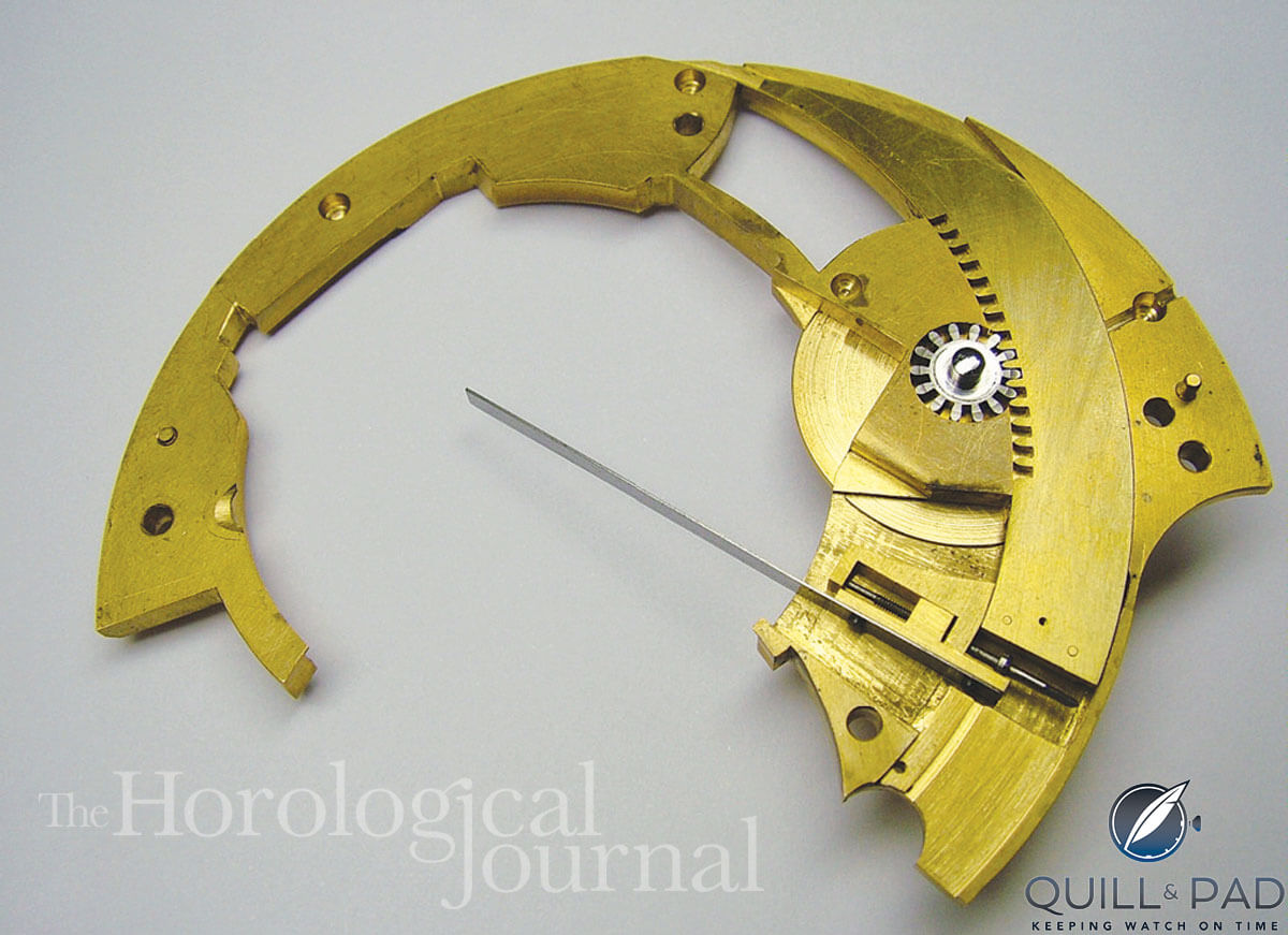
Derek’s rack and pinion regulator for Derek Pratt’s H4
The original H4 still has the pinion on which the regulator disc is mounted but the rack is missing. It was decided to make the copy as H4 is now without the rack. Although the rack and pinion are convenient for regulating, Harrison must have found it liable to move and upset the rate. The watch is now free sprung and has an elaborate mounting for the balance spring stud. The stud is mounted in such a way that it can be adjusted in any direction; this helps in positioning the center of the spring so that the balance staff stands upright when at rest.
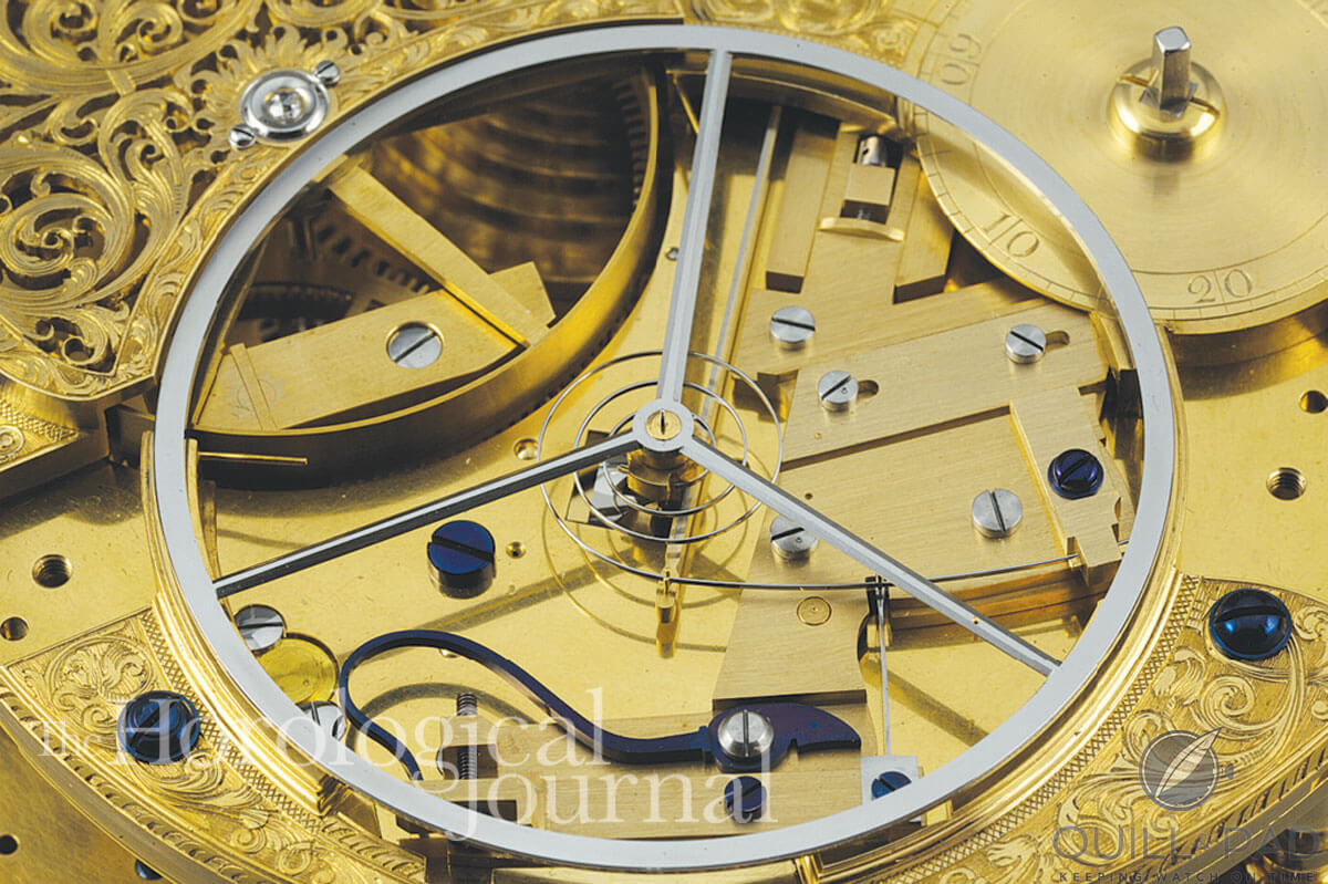
Adjustable mounting for the balance and spring for Derek Pratt’s H4
The temperature compensation curb consists of a brass-and-steel strip held together with 15 rivets. The curb pins at the end of the compensation curb embrace the spring and as the temperature rises the curb will bend to shorten the effective length of the spring.
Harrison had hoped to adjust for isochronal errors using the shape of the backs of the pallets, but he found this was insufficient and he added what he called a ‘cycloid’ pin. This is adjusted to come into contact with the tail of the balance spring and quicken the vibration at the chosen amplitude.
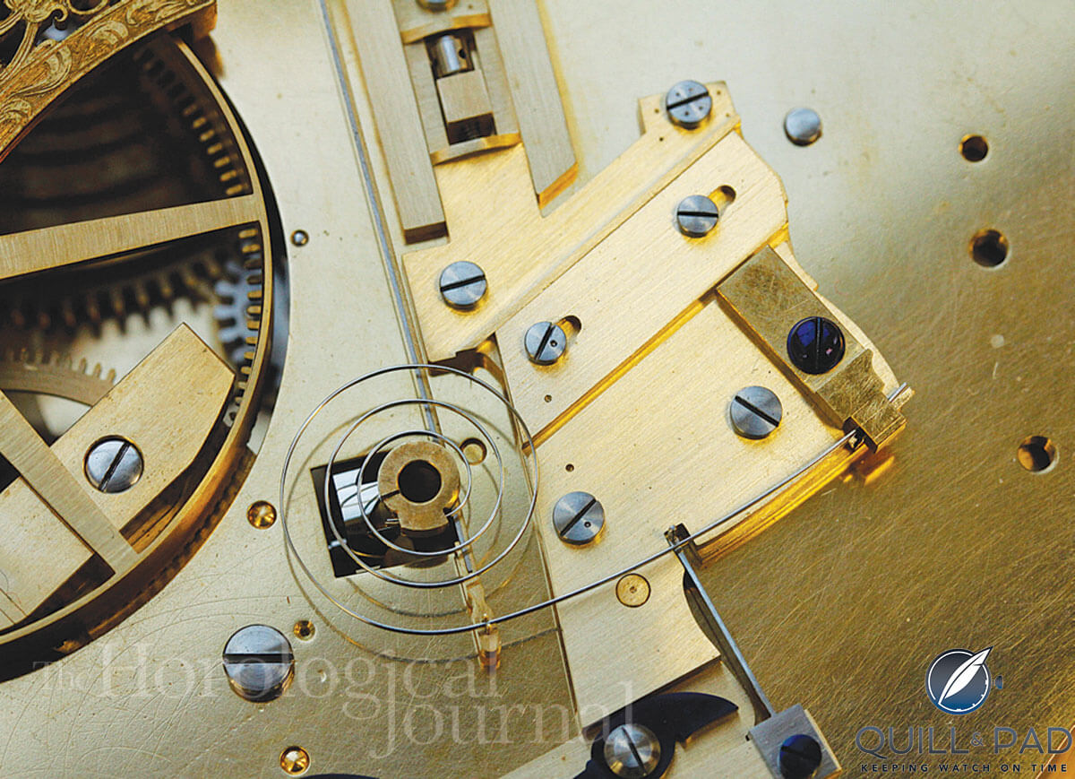
Adjustable cycloid pin that interacts with the balance spring for Derek Pratt’s H4
All the compensation parts were given a grained finish and the steel parts blued as appropriate.
At this stage the top plate was given to Charles Scarr for engraving. Derek had requested that the plate be engraved as the original but with his name on the edge of the slide plate and the third wheel bridge, adjacent to the Harrison signature. The inscription reads: “Derek Pratt 2004-Chas Frodsham & Co AD2014.”
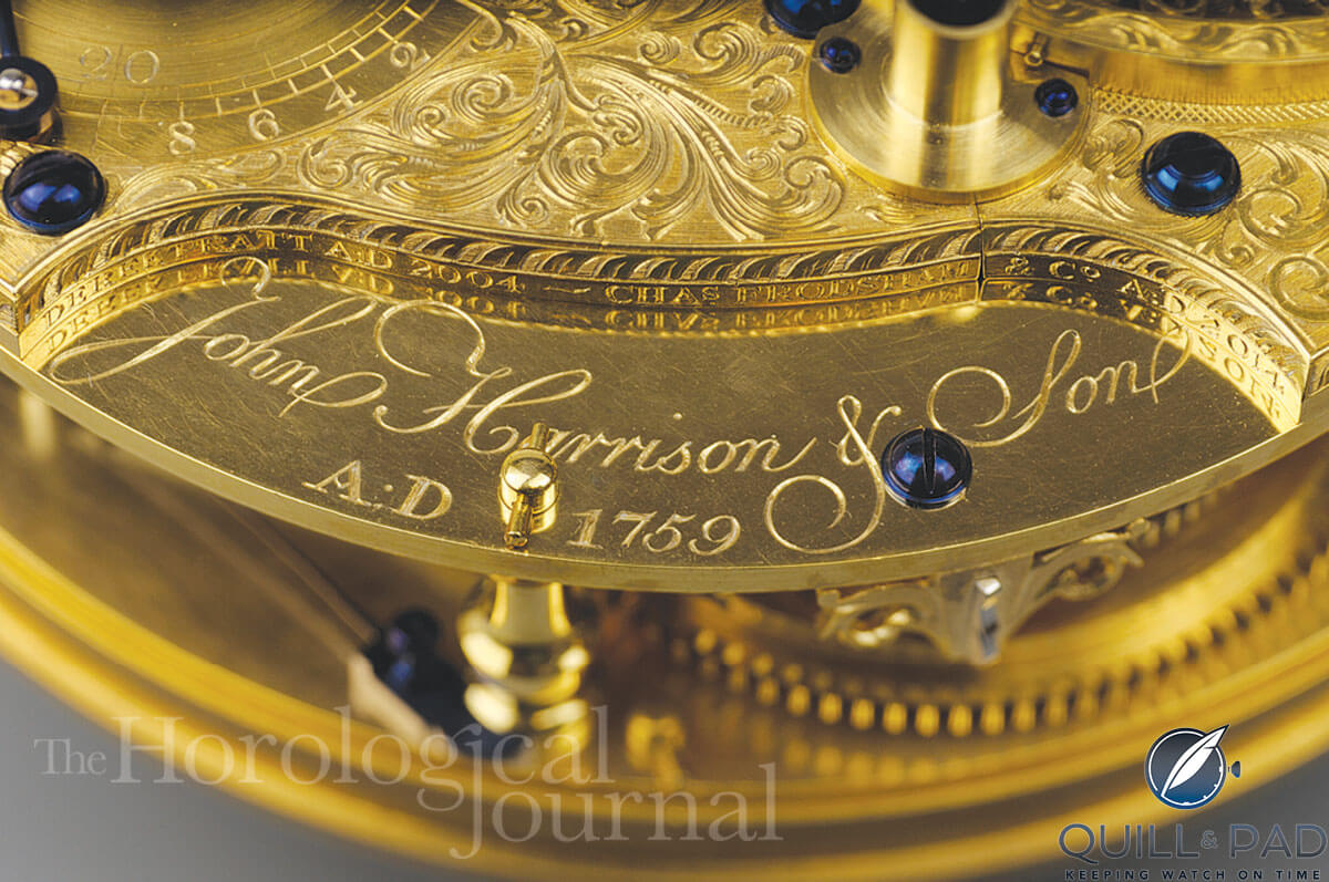
Inscription: “Derek Pratt 2004 – Chas Frodsham & Co 2014” for Derek Pratt’s H4 reconstruction
Timing
Having made the balance spring close to the dimensions of the original spring, the watch was brought to time by removing material from the underneath of the balance wheel, the wheel being left slightly thicker to allow for this. The Witschi watch timer was very useful in this regard, as it can be set to measure the frequency of the watch after each adjustment.
The balance was poised using the nicely ground jaws of a “star” vice.
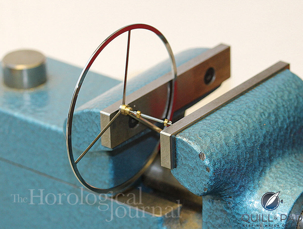
Poising the balance for Derek Pratt’s H4
This was somewhat unconventional but provided a means of poising such a large balance. As weight was slowly removed from the underneath of the balance the frequency got closer to 18,000 beats per hour and the timer was then set to 18,000 and the watch’s error could be read.
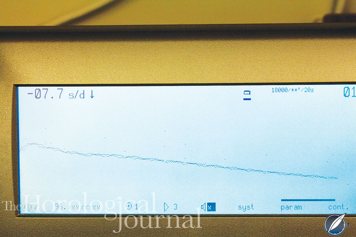
Witschi timing machine trace of Derek’s H4 starting from minimum amplitude for Derek Pratt’s H4
The image above shows the trace when the watch was started from a low amplitude and then quickly settled to its running amplitude with a steady rate. The trace also shows the rewinding of the remontoir every 7.5 seconds. The watch was also tested on an old Greiner Chronographic watch timer using a paper trace. This machine has the facility to be set to run slow, when the paper feed is ten times slower and the error is magnified by ten. This setting is convenient to test a watch for an hour or more without becoming knee deep in paper!
The long run tests did show some variation in rate and the drive to the center seconds was found to be quite critical, as it required oil where it bears on the cannon pinion, but it needed to be a very light oil in order not to cause too much drag and reduce the balance amplitude. The lowest viscosity watch oil we could find was Moebius D1 with a viscosity of 32 centistokes at 20°C; this worked well.
The watch has no mean-time adjustment as was later fitted in H5, and so it was tempting to make small adjustments of the cycloid pin in order to make fine adjustments to the rate. The cycloid pin was tested at different positions, contacting the spring sooner or later in its breathing and also with different gaps at the curb pins.
There did not seem to be an ideal position but it was set where the change in rate with changing amplitude was at its least. The change of rate with amplitude shows that the remontoir is necessary in smoothing the impulse to the balance. Unlike James Poole, we think the remontoir is really useful!
The watch was running by January 2014, but there were still some adjustments needed. The power available at the escapement is dependent on four different springs in the watch and these all have to be in balance with each other: the mainspring, maintaining power spring, remontoir spring and the balance spring. The mainspring can be set up as required and then the maintaining spring, which provides the torque whilst the watch is being wound, has to be sufficient to re-wind the remontoir spring fully.
The amplitude at the balance is dependent on the set-up of the remontoir spring. There were a few adjustments needed, particularly between the maintaining spring and the remontoir spring, in order to get the balance right and have sufficient power at the escapement. Every adjustment of the maintaining spring meant dismantling the whole watch.
The watch went to Greenwich to be photographed and filmed in February 2014 for the “Quest for Longitude–Ships Clocks and Stars” exhibition. The resulting video on display at the exhibition gave a very good description of the watch and shows each part being assembled.
A period of testing followed and adjustments were made before the watch was delivered to Greenwich in June 2014. There wasn’t time for a proper temperature test and the watch was found to be overcompensated, but with it running at a fairly even temperature in the workshop, it kept within plus or minus two seconds per day when it had an undisturbed run for nine days. In order to win the £20,000 prize it would need to keep time to within plus or minus 2.8 seconds per day for the six-week voyage to the West Indies.
Conclusion
Finishing Derek Pratt’s H4 has been an exciting project with many challenges. At Frodshams, we have always held Derek in the highest regard, both as a watchmaker and as such a pleasant person with whom to work. He was always generous in sharing his knowledge and his time in order to help others.
Derek’s workmanship was excellent and he devoted much time and effort to progress his H4 project in spite of the many challenges he faced. We think he would be pleased with the end result and delighted that the watch is on display for everyone to see.
The watch was displayed at Greenwich from July 2014 to January 2015 along with all five original Harrison timekeepers and many other interesting pieces. The exhibition, along with Derek’s H4, now embarks on a world tour, starting at The Folger Shakespeare Library, Washington DC, from March to September 2015; followed by Mystic Seaport, Connecticut, from November 2015 to April 2016; and then to the Australian Maritime Museum, Sydney, from May 2016 to October 2016.
Acknowledgements
Finishing Derek’s H4 has been a team effort by all at Frodshams and we also received valuable help from Anthony Randall, Jonathan Hird, and a number of others in the horological world, who assisted both Derek and ourselves in completing this project. I would also like to give particular thanks to Martin Dorsch for help with the photography for these articles.
Quill & Pad also wishes to thank The Horological Journal for allowing us to republish this series of three articles here. If you missed them you may also enjoy:
The Life And Times Of Legendary Independent Watchmaker Derek Pratt
Derek Pratt’s Reconstruction Of John Harrison‘s H4, The World’s First Precision Marine Chronometer (Part 1 of 3)
Making The Diamond Pallets For Derek Pratt’s Reconstruction Of John Harrison‘s H4, The World’s First Precision Marine Chronometer (Part 2 of 3)
Trackbacks & Pingbacks
-
[…] You will find Part 2 at Making Diamond The Diamond Pallets For Derek Pratt’s Reconstruction Of John Harrison’s H4, The World’s First Precision Marine Chronometer (Part 2 of 3) and part 3 at Making The Escapement, Remontoir, And Timing For Derek Pratt’s Reconstruction Of John Harrison‘s…. […]
-
[…] To learn more about Derek Pratt please see The Life And Times Of Legendary Independent Watchmaker Derek Pratt. For part 1 in this series click Derek Pratt’s Reconstruction Of John Harrison‘s H4, The World’s First Precision Marine Chronometer (Part 1 of 3) and for part 3 click Making The Escapement, Remontoir, And Timing For Derek Pratt’s Reconstruction Of John Harrison‘s…. […]
Leave a Reply
Want to join the discussion?Feel free to contribute!



Sorry. I am looking for my school friend, Martin Dorsch, a German watchmaker from Regensburg. If you know him, could you forword my contact possibilities to him. Thanks!
Junwoo JEONG
Am Waisenhausplatz 4, 75172 Pforzheim, Germany
Email: [email protected]
Tel: 0049 (0)174 76 35 227
We don’t know him, but if we ever meet him, we’ll be sure to point him to this comment.